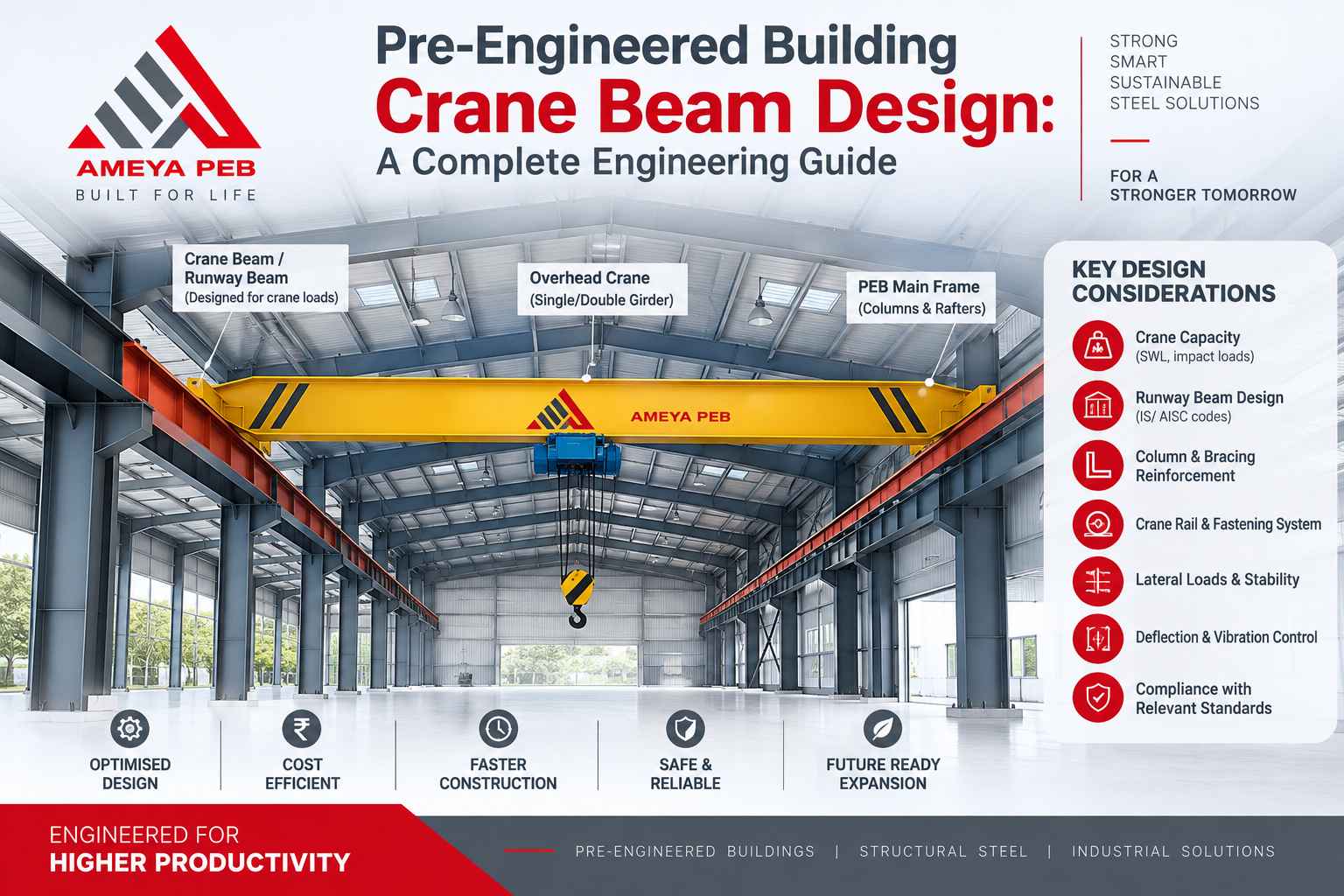
Anyone who has walked through a working factory floor with an overhead crane rolling past knows the sound before they see it — that low, steady rumble of wheels on rail. Behind that simple movement sits a beam that has to survive a punishment most structural members never face: repeated, moving, unpredictable loads, thousands of times a day, for decades. In a pre-engineered building (PEB), designing that beam correctly is not optional. Get it wrong and you're not looking at a cosmetic crack — you're looking at fatigue failure, rail misalignment, or worse.
What Makes a Crane Beam Different from a Regular Beam
A standard roof purlin or floor beam deals with loads that are, for the most part, static and predictable. A crane beam — often called a crane runway girder — deals with:
- Moving concentrated loads that shift position continuously along the span
- Impact and vibration from wheel loads striking rail joints
- Lateral (side) thrust from crane acceleration, braking, and skewing
- Longitudinal tractive forces from the bridge motor
- Fatigue cycling, since the load isn't applied once — it's applied thousands or millions of times over the structure's life
Because of this, crane beams are designed against a completely different failure mode than gravity beams: fatigue, not just strength. A beam that passes a one-time strength check can still fail after ten years of cyclic loading if fatigue wasn't considered.
Key Load Cases an Engineer Must Combine
Designing a PEB crane beam means combining several load types that rarely get discussed together in a general steel design course:
- Vertical wheel loads — the maximum wheel load from the crane, positioned to produce the worst-case bending moment (usually derived by placing the crane at the location that maximizes moment using the absolute maximum moment method or influence line analysis).
- Impact factor — an amplification applied to vertical loads to account for dynamic effects of a moving crane. This typically ranges from 10% to 25% depending on crane class and speed, per codes like IS 875 Part 2 or AISC/CMAA specifications.
- Lateral surge (side thrust) — a horizontal force applied at the top of rail, generally taken as a percentage of the sum of the lifted load and trolley weight, resisted by the top flange or a separate crane surge girder.
- Longitudinal tractive force — from crane bridge braking, applied along the rail direction and transferred to the column bracing system.
- Fatigue loading — cyclic stress range checks based on crane duty class (light, medium, heavy, or severe duty per CMAA or FEM classification).
Most design mistakes in PEB crane systems trace back to skipping one of these — usually lateral surge or fatigue — because the vertical load case looks like it governs on paper.
Crane Duty Classification Drives Everything
Before a single calculation begins, the crane's duty class needs to be nailed down. This isn't a minor spec detail — it changes allowable stress ranges, fatigue categories, and even which design code provisions apply.
Common classifications (CMAA Specification 70/74, widely referenced in PEB projects):
- Class A/B (Light/Standby) — infrequent operation, light loads, such as maintenance bay cranes
- Class C (Moderate) — general manufacturing with moderate use
- Class D (Heavy) — mills and heavy manufacturing running at or near capacity regularly
- Class E/F (Severe) — continuous, high-cycle operation such as steel mills or bulk material handling
A crane beam sized correctly for Class A duty will fail prematurely under Class E cycling, even if the peak load is identical. This is the single most overlooked variable in PEB crane beam design.
Section Selection: Why Built-Up Sections Dominate
In light-duty PEB sheds, a rolled wide-flange section is sometimes adequate. But once spans stretch beyond roughly 6–8 meters or duty class climbs, engineers typically shift to a built-up plate girder, often with a channel cap or separate surge girder welded or bolted to the top flange.
Why the top flange gets reinforced:
- It resists both vertical bending and lateral bending from surge simultaneously — a biaxial bending condition.
- Torsional effects from eccentric wheel loading (since the rail rarely sits perfectly over the web centerline) add stress that a simple I-section can't handle efficiently.
- A wider top flange or capping channel increases lateral stiffness without adding unnecessary depth to the whole girder.
The bottom flange, by contrast, usually only sees vertical bending and can stay narrower — one of the more elegant efficiencies in crane beam design.
Deflection Limits Are Stricter Than You'd Expect
Ordinary floor beams might be allowed a deflection limit of span/240 or span/360. Crane runway beams are held to a tighter standard — often span/600 to span/1000 depending on crane speed and duty — because excessive deflection causes:
- Rail misalignment and accelerated wheel wear
- Increased dynamic impact as the crane "rides" an uneven track
- Operator discomfort and reduced crane travel speed in practice
For high-speed or precision cranes (such as those in steel processing lines), deflection often governs the design more than bending stress does.
Fatigue Design: The Step Many Skip
Fatigue is checked using stress range (not peak stress) against an allowable range that depends on the connection detail category — a welded flange-to-web joint behaves very differently from a bolted splice under repeated loading. AISC Appendix 3 and similar provisions in IS 800 and Eurocode 3 classify details into categories, each with its own allowable stress range curve.
Two design decisions matter most here:
- Avoid welded attachments on the tension flange wherever the crane travels directly overhead, since weld toe stress concentrations are prime fatigue initiation points.
- Use smooth transitions at flange splices and stiffener terminations rather than sharp geometric changes.
Skipping fatigue verification is the most common reason crane beams that "passed design" later develop cracks at flange-to-web welds within a few years of operation.
Column and Bracket Interaction
The crane beam doesn't act alone — it sits on brackets or corbels attached to the main PEB columns, and that connection needs its own scrutiny:
- The bracket must transfer vertical reaction, lateral surge, and longitudinal tractive force independently.
- Column stepped sections (common in PEB crane buildings) need separate stiffness checks for the crane column segment versus the roof column segment above the bracket.
- Anchor bolt and base plate design at the column foundation must account for the crane-induced overturning moment, which can be substantial for outdoor or heavy-duty cranes.
Practical Design Checklist
Before finalizing a PEB crane beam, run through this sequence:
- Confirm crane duty class and wheel load data from the crane manufacturer (never assume — always request certified data)
- Determine span and rail center-to-center distance
- Calculate maximum vertical moment using influence line or absolute maximum moment method
- Apply appropriate impact factor
- Design top flange/cap channel for combined vertical + lateral bending
- Check web for local buckling and bearing stress under wheel loads
- Verify deflection against span/600–span/1000 limits
- Perform fatigue stress-range check at all welded and bolted details
- Design bracket/corbel connection for all three force directions
- Coordinate with column design for combined crane and gravity loads